Machining a Large Weldment After Welding: Datums and Stock Allowance
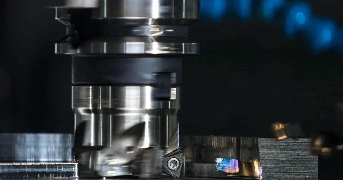
A welded frame that has to carry bearings, rails or a gearbox is not finished when the last weld is ground. It is finished when the mounting faces have been machined flat, square and to the right height from a clear reference. The welding only builds the blank. Machining after welding makes the part.
Two decisions control how well that works: how much steel is left on the faces to be machined, and which features the machinist treats as the reference. Both are often left to the shop, and both are cheaper to settle before steel is cut than after the frame is on the machine table.
Why allowance is not optional
A welded frame is never exactly the shape of the model. Weld shrinkage pulls plates inward, long welds bow flanges, and plate thickness varies within the mill tolerance. A 3 metre frame can finish a few millimetres out of the nominal shape before any machining. If the drawing gives a machined surface at an exact size and the blank has no extra material, the cutter will miss low spots entirely and leave a patch of black scale in the finished face.
The allowance is the extra thickness, left on every face that will be machined, that absorbs this variation. It must be large enough that the cutter cleans up the whole face, and small enough that machine time and material cost stay sensible.
Typical allowance by frame size
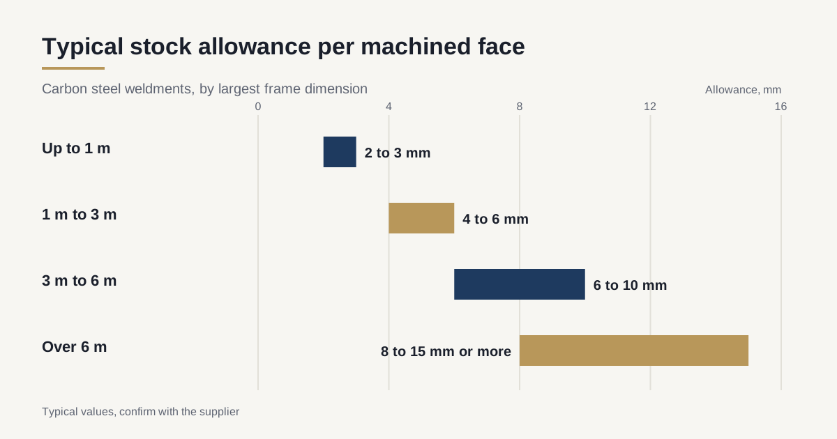
There is no universal figure. The right allowance depends on frame length, plate thickness, weld volume and whether the frame is stress-relieved before machining. As a starting point for carbon steel frames:
| Largest dimension of the frame | Typical allowance per machined face | Notes |
|---|---|---|
| Up to 1 m | 2 to 3 mm | Light welding, little distortion |
| 1 m to 3 m | 4 to 6 mm | Common range for machine bases and skids |
| 3 m to 6 m | 6 to 10 mm | Heavy weld volume, plan for rough and finish passes |
| Over 6 m | 8 to 15 mm or more | Often split into sections to hold tolerance |
These are typical values and the shop’s own experience with its welding procedure should refine them. A shop that has built similar frames will give you a number quickly. A shop that cannot explain its allowance has probably not controlled its distortion either.
Too much allowance has a cost. Every extra millimetre on a 2 m by 1 m face is 2,000 cubic centimetres of steel turned into chips and several extra machine passes. Too little is worse, because a frame scrapped for lack of stock is a schedule and material loss.
Datums: telling the machinist where to start
A datum is a surface, line or point from which other dimensions are measured. On a machined weldment, the datum scheme tells the machinist which surface to machine first, which to hold against the table and which tolerances are measured from which.
Good datum choice follows the way the frame is used:
- Primary datum: the large mounting face that sits on the foundation or the machine bed. It sets flatness and height.
- Secondary datum: a face or bore that fixes the frame in the horizontal plane, usually a side face or the centre line of the main bearing bore.
- Tertiary datum: a third reference that stops rotation, often an end face.
Flag datum features on the drawing with a datum symbol and call the geometric tolerances from them. The drawing should state a datum for every critical dimension. A machinist who has to guess which face is the reference will choose the one that is easiest to hold, which may not be the one that matters to the assembly. See the discussion of flatness callouts in the article on flatness tolerance for large machined weldments.
The machining sequence that holds tolerance
The order of operations matters more than the machine. A reliable sequence for a stress-relieved frame looks like this:
- Inspect the blank. Measure the unmachined frame on a surface plate or with a laser tracker. Check that every face to be machined has at least the minimum allowance.
- Rough machine the datum faces. Remove most of the stock, leaving 0.5 to 1 mm for the finish pass.
- Relieve or rest. For thick sections or heavy cuts, a second stress relief or a rest period lets the frame settle before the final pass.
- Reclamp lightly. Release the clamps and clamp again with minimum force so the frame is not pulled flat by the fixture and then springs back.
- Finish machine the datum faces. Machine primary, then secondary, then tertiary, in the order set by the datum scheme.
- Machine the dependent features. Bores, slots and secondary faces are machined from the finished datums in one setup where possible.
- Inspect at stable temperature. Measure the finished frame after it has equalised to workshop temperature, not straight off the machine.
The reasoning behind step 3 is explained in the article on stress relief for welded machine bases. Machining before relief wastes the work, and relieving after finish machining undoes it.
Fixturing and clamping
Large frames flex under their own weight and under the clamps. A frame forced flat on the table, then machined flat, will spring back to its natural shape when released and the machined face will no longer be flat. This is the most common cause of a part that measured correct on the machine and wrong at final inspection.
Good practice is to support the frame on three points or on adjustable jacks under the primary datum, to clamp only enough to resist the cutting force and to check the frame with an indicator before and after clamping. If the indicator moves more than a few hundredths of a millimetre when the clamps are tightened, the fixturing is distorting the part.
Weight is a practical limit. Many heavy frames weigh 5 to 30 tonnes, and the machine table must carry that weight and still cut accurately. Ask about the table load rating, the crane capacity over the machine and the travel in each axis. A shop that has to split a job across two machines will lose the shared reference between them.
Machine capability and measurement
Large weldments are machined on floor-type boring mills, portal machines, planer-type mills or large vertical turning machines, depending on shape. Ask three things:
- Is the machine large enough to cut every feature in one setup?
- How is accuracy checked, and when was it last verified?
- Does the shop measure on the machine with a probe, or move the frame to a separate inspection area?
On-machine probing avoids resetting the part and keeps the shared datum. Separate inspection with a laser tracker or a coordinate measuring arm gives independent proof. Both are valid, and the best shops use both. More on large-part inspection is in the article on dimensional inspection with laser trackers and CMMs.
Temperature matters. Steel expands about 12 micrometres per metre per degree Celsius, so a 4 m frame that is 5 degrees warmer than the reference will measure about 0.24 mm longer. Large-frame inspection is normally referred to 20 degrees Celsius, so ask when the measurements were taken and how the frame was equalised.
Common mistakes
Allowance only on some faces. The drawing marks the main face for machining, but the dependent bearing seats sit on unmachined plate. Mark every machined face.
Welding after rough machining. Adding a late weld for a missing bracket shifts the geometry and sends the frame back to relief.
Datums on welded surfaces. A datum that sits on an as-welded face moves with every weld. Put datum features on machined or at least ground surfaces.
No stock check before machining. A frame that arrives with short stock on one face can sometimes be saved by shifting the machining plane, but only if someone checks before the first cut.
What to put on the drawing
- Surfaces to be machined, marked with the machining symbol.
- A machining allowance note, such as “Leave 5 mm stock on all machined faces”.
- Datum features and the tolerance frames that reference them.
- Sequence note: “Stress relieve before machining” when that is required.
- Final inspection temperature and method, for example “Measure at 20 degrees Celsius with a laser tracker”.
Closing checklist
- Allowance agreed per face and compared with expected weld distortion.
- Datum scheme drawn and understood by the shop.
- Stress relief placed before rough machining.
- Machine table capacity, travel and crane reach confirmed.
- Inspection method and temperature stated.
A weldment that is machined well looks easy. The work was in the allowance, the datums and the sequence. If you have a frame with machined faces and want to know which shops can hold the tolerance, send the drawing and we will reply within 24 business hours. For the wider picture on how machined weldments compare with other routes, see machined weldment vs casting for a machine base.