Generator and Compressor Base Frames Built for Export
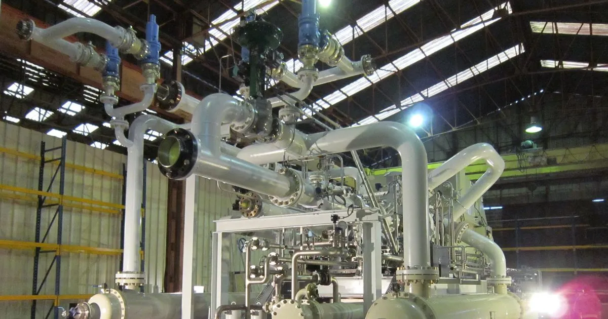
An engine, an alternator or a compressor weighs several tonnes and shakes. The base frame under it has to hold the machine in precise alignment, carry its weight, survive lifting and ocean transport and stay flat enough that the machine can be bolted down without stress. A frame that looks right but moves a fraction of a millimetre under the first engine foot can cause misalignment, vibration and early bearing wear.
Equipment makers in the US, Europe and Australia source base frames from overseas fabricators because the work is steel-intensive and the geometry is repeatable. This article explains what to specify so that a base frame built abroad fits the machine when it arrives.
What the frame has to do
A base frame has five jobs:
- Carry the static weight of the engine, alternator or compressor and its auxiliaries.
- Hold alignment between the driving and driven machines, usually joined by a flexible coupling.
- Resist dynamic loads from rotating and reciprocating parts, and from starting torque.
- Provide lifting and transport points for the complete package or for the frame alone.
- Mount to the foundation or to vibration isolators with a stable interface.
Frames for gensets are often built as a skid of two long main beams joined by cross members, with an integrated fuel tank in some designs. Compressor skids add oil systems, coolers and piping supports. The shared design logic of heavy skids is covered in the article on equipment skid design: beam sizing and lifting lugs.
Frame types and typical features
| Frame type | Typical features | Fabrication focus |
|---|---|---|
| Open skid | Two main beams, cross members, machined pads | Flatness of pads, torsional stiffness |
| Fuel tank base | Beams with an integral steel tank between them | Leak test, internal cleanliness, venting |
| Canopy base | Base frame with provisions for an enclosure | Dimensions, drain and cable entry points |
| Compressor skid | Heavier beams, oil console supports, piping stands | Stiffness, access, weld quality for fatigue |
Pad flatness and alignment
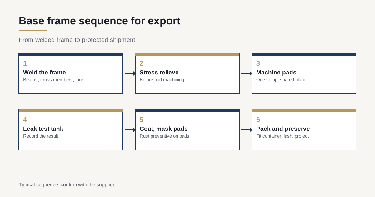
The engine feet and alternator feet rest on machined pads. If the pads are not coplanar, the machine twists when bolted down and the crankshaft or rotor ends up misaligned. Typical practice is to weld the frame, stress relieve it and then machine all pads in one setup so that they share a plane.
Typical machining targets for mounting pads on medium frames are coplanarity within about 0.10 to 0.25 mm across the pad group and surface finish of Ra 3.2 micrometres or better, with the engine or compressor builder setting the actual limits. Pad thickness allowance before machining depends on the frame length and weld distortion. See the article on post-weld machining allowance for typical stock and datum choices.
Ask who sets the pad tolerances. The engine maker’s installation drawing is the best source. If it is not available, the frame maker should ask for it before cutting steel.
Vibration mounts and foundation interface
Gensets are frequently mounted on anti-vibration mounts, either between the engine and the frame or between the frame and the floor. Compressor skids are more often bolted and grouted. The frame has to carry the mounts without local deflection.
Points to specify:
- Mount positions and bolt hole pattern, with tolerances.
- Reinforcement plates under mounts and under the engine feet.
- Mount type and thickness, because mount height changes the frame’s overall height.
- Foundation bolt holes or anchor slots, with enough slot length to adjust on site.
- Grouting provisions such as grout holes and flat bottom surfaces, for grouted skids.
Integrated fuel tanks
A common genset design uses the base frame as the fuel tank, with a sealed steel box between the main beams. This saves space and cost, and it adds specific requirements.
- Leak test. The tank is tested after welding, commonly with low air pressure and a soap solution, or with water, to a pressure the design states. Confirm the test method with the design and record the result.
- Internal cleanliness. Weld spatter, scale and debris must be removed. Particles in a diesel tank clog filters. Blasting and flushing may be needed.
- Baffles and vents. Internal baffles reduce fuel slosh, and vent and breather connections must be positioned correctly.
- Fuel connections and level gauge fittings, with thread type and position on the drawing.
- Coating. Interior coating or a clean uncoated finish, as the design requires. Never use a coating that is incompatible with diesel.
Welds on a tank must be continuous and sealed. A tank frame is a pressure-tested vessel in a small way, and it deserves proper inspection records.
Lifting and transport design
The frame is lifted several times: at the fabricator, at the equipment maker’s plant, on and off a truck or ship and at the site. Lifting points must be designed for the complete package weight, not only for the empty frame.
- Lifting lugs or eyes, sized with a safety factor and tested if required by the specification. See the article on equipment skid lifting lug design.
- Centre of gravity marked on the frame and noted in the documents. Engine and alternator positions move it away from the geometric centre.
- Forklift pockets where lifting by truck is expected.
- Tie-down points for lashing during shipment.
Spreader beams may be needed. A package that must be lifted with a four-point sling needs lugs placed to keep the machine level.
Fit for container or flat rack
Export frames travel in sea containers or on flat racks. A frame that is 5 mm too wide for the container door cannot be loaded.
| Container | Typical internal length | Internal width | Internal height |
|---|---|---|---|
| 20 ft standard | 5.90 m | 2.35 m | 2.39 m |
| 40 ft standard | 12.03 m | 2.35 m | 2.39 m |
| 40 ft high cube | 12.03 m | 2.35 m | 2.69 m |
These are typical internal sizes, and the door opening is smaller than the interior, with the high cube door opening about 2.58 m high. The frame and any equipment on it must fit with clearance for lashing and for forklift entry. When the package is wider or taller than a container allows, flat rack or breakbulk shipment is required, as explained in the article on out-of-gauge breakbulk shipping. The design question of splitting a large frame into shippable pieces is covered in the article on split-and-bolt frame design.
Coating for ocean transit and site life
Generators and compressors often go to coastal sites, mines and offshore platforms. The coating must survive the voyage and the first years of operation. The choice, whether paint, galvanising or a combination, is covered in the article on surface finish systems for structural steel. Specific points for base frames:
- Machined pads are not painted. They carry a rust preventive and a protective cover until the machine is installed.
- Underside and cavities get the same coating as the visible surfaces, because condensation in a closed container attacks hidden steel first.
- Touch-up paint is shipped with the frame and applied after installation.
- Drain holes in the beams allow water to leave.
Preservation and packing
A frame that sits at a port for three weeks and then on a ship for five is exposed to humidity swings. Machined surfaces, threaded holes and bolt threads need protection.
- Rust preventive applied to all bare machined surfaces.
- Plugs and caps in threaded holes and fuel connections.
- Vapour corrosion inhibitor paper or emitters where the frame is wrapped.
- Desiccant in sealed packages, with humidity indicators.
- Blocking and bracing so that the frame cannot shift.
Incoterms and handover
The frame’s responsibility and risk pass at a defined point, set by the Incoterm. For export frames this is usually EXW, FOB or CIF, and the loading and lashing details differ. See the article on Incoterms for heavy fabrication.
What to write on the order
- Frame drawing with pad flatness, hole patterns and tolerances.
- Material grade and certificates.
- Stress relief before machining pads.
- Tank requirements, with test method and cleanliness standard, if applicable.
- Lifting design, with package weight and centre of gravity.
- Container or flat rack target, with maximum envelope.
- Coating and preservation specification.
- Documentation: inspection report, weld records, tank test record, certificates.
Checklist before shipment
- Pad flatness measured and recorded.
- Tank leak test passed, if fitted.
- Lifting points checked against the full package weight.
- Frame fits the container or flat rack with clearance.
- Machined surfaces preserved.
- Marks, centre of gravity and lifting instructions on the frame.
For scope, lifting, containment and acceptance on any equipment skid, see the steel skid fabrication guide.
If you build generator sets or compressor packages and want a quote on base frames, send the drawing with the machine installation drawing if you have it. We reply within 24 business hours.