Line Boring Bearing Housings on Large Steel Frames
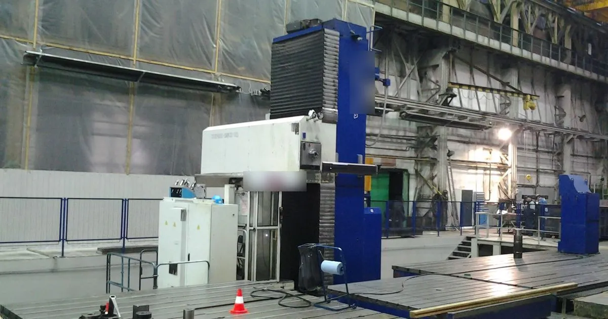
A shaft that runs through three or four bearings only runs well if the bearing seats lie on the same axis. On a large welded frame, those seats sit in different plates, sometimes several metres apart. Machining each one separately, in separate setups, leaves small errors that add up: a bearing that carries more load than its neighbour, a belt that wanders, a gearbox that runs hot.
Line boring is the answer. One boring bar, one setup, one axis, all the bores machined in a single pass sequence. This article explains how it works on large steel frames, what accuracy is realistic and what a buyer should write on the drawing.
What line boring means
Line boring is machining of several bores that must be coaxial, using a rotating boring bar that passes through all of them or is moved from one to the next without resetting the workpiece. The axis of the bar becomes the axis of the bores, so all of them share it by construction.
The alternative is to machine each bore from a separate setup, using the frame’s outer faces as the reference. On a small part this works. On a frame several metres long, the frame’s own distortion, the machine’s travel error and the re-clamping all add error between bores.
There are two common ways to do it on a fabricated frame:
- On a floor-type horizontal boring mill. The frame sits on the floor plate or a fixture, and the spindle or a fixed boring bar passes along the axis. This is the standard route for new-build frames.
- With a portable line boring machine. A bar is set up through the frame in place and rotated by a drive unit. This is common for repair work and for very large frames that cannot be moved onto a machine.
Both can reach high accuracy when the setup is rigid and well measured.
Typical accuracy
Realistic targets depend on bore diameter, span between bores and machine condition. As typical figures for good practice on large steel frames:
| Characteristic | Typical achievable range | Comment |
|---|---|---|
| Bore diameter tolerance | ISO 286 H7, for example 0 to +0.05 mm on a 300 mm bore | Tighter needs temperature control |
| Coaxiality between housings | 0.03 to 0.10 mm over a few metres | Lower end needs a single setup and a rigid bar |
| Cylindricity | About half the diameter tolerance | Affected by tool wear and bar deflection |
| Surface finish in the bore | Ra 1.6 to 3.2 micrometres | Finer finish possible with a finishing pass |
| Squareness of shoulders to axis | 0.02 to 0.05 mm over the shoulder face | Needs facing from the same setup |
Do not specify tighter than the bearing needs. Bearing manufacturers’ catalogues give recommended housing tolerances for each bearing type and load. A spherical roller bearing in a heavy frame typically accepts a looser alignment than a pair of tapered roller bearings on a rigid shaft, because the bearing itself can tolerate some misalignment.
Why the frame must be stable first
Boring is only as good as the frame it is cut into. If the frame is still moving, the bores will move with it. Two preparations matter.
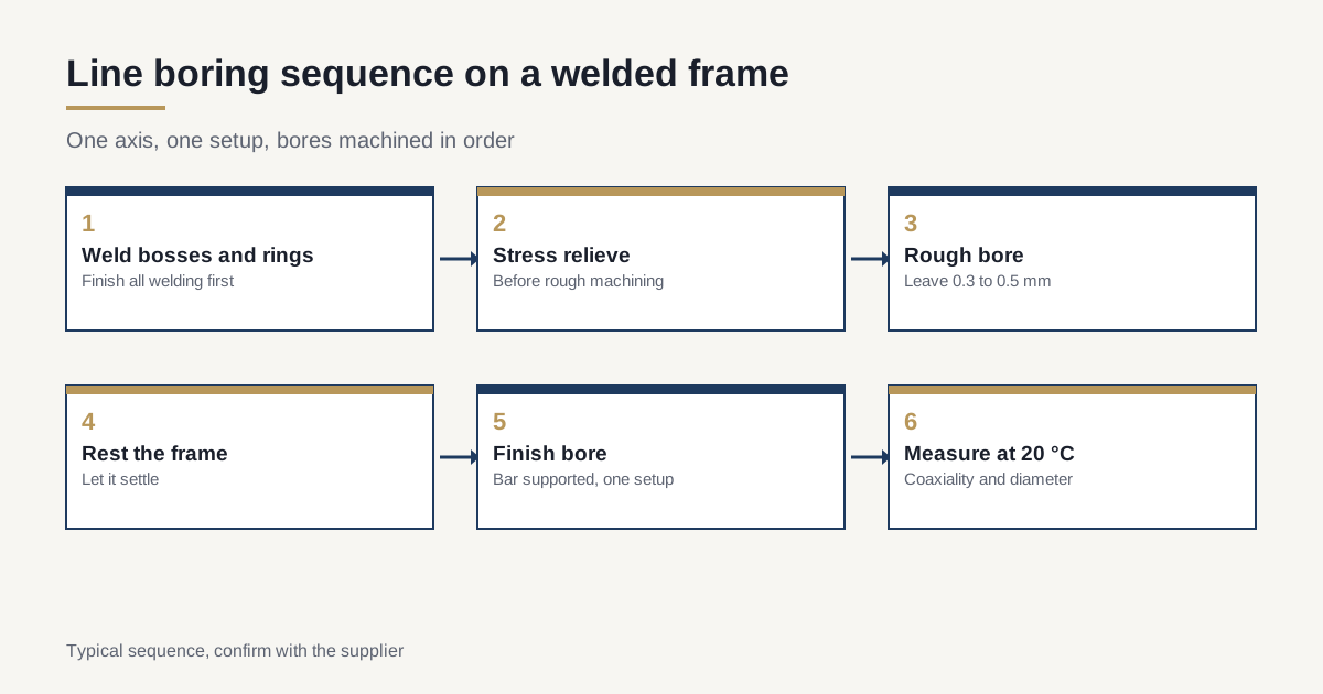
Stress relief before boring. A welded frame holds residual stress, and removing metal from the bore walls releases some of it. The frame can twist slightly after the last cut. Thermal stress relief before rough machining, and a rest period before the finish pass, protect the alignment. The reasoning is covered in the article on stress relief for welded machine bases.
Machined datums. The frame should be supported and referenced from machined faces, not welded surfaces. The principles on datums and allowance are in the guide to post-weld machining allowance.
Stock allowance for bores
A welded bearing housing starts as a rough hole, either flame-cut or drilled, in a thick plate or a welded boss. The allowance left for boring is typically 3 to 6 mm on the radius for rough machining on a large bore, with 0.3 to 0.5 mm left for the finish pass. Too little and the cutter leaves black spots where the weld distorted the hole. Too much and the boring bar works hard and heats the part.
Welded-in rings and bosses are common. They are cut, fitted and welded into the frame before boring so the welding distortion is finished before the bore is cut. Welding a ring after boring defeats the purpose.
Setup: bar, supports and sag
A long boring bar behaves like a beam. Supported only at one end, it sags under its own weight and under cutting force. A bar that is 3 m long and 150 mm in diameter can deflect enough to cause a taper in the far bore. Shops use three techniques to control it.
- Support at both ends. The bar runs in bushings or bearings at each end of the frame, and the tool cuts between them.
- Short overhang. The bar enters from one side and is shortened for each housing.
- Rigid bar material and diameter. Larger-diameter bars deflect less.
The fabricator should be able to describe which approach is used for your span. A shop that has done similar frames will answer in a sentence. A shop that has not may promise a tolerance it cannot hold.
Measurement
Bore diameter is measured with an internal micrometer, a bore gauge or an air gauge. Coaxiality is harder. Typical methods are:
- A mandrel or precision bar through all bores, with indicators at each housing.
- A laser alignment system that projects a line through the bores and measures offsets at each housing.
- A laser tracker or measuring arm that fits a cylinder to each bore and calculates the axis for each, then compares them. See the article on dimensional inspection with laser trackers and CMMs.
Measure at stable temperature. Steel moves about 12 micrometres per metre per degree Celsius, so a 4 m frame that has warmed 3 degrees has grown more than 0.1 mm along the axis. For tight work, the frame sits in a controlled hall for several hours before the finish pass, and the measurement is referred to 20 degrees Celsius.
Split housings and caps
Many large bearings sit in a split housing: a base in the frame and a cap bolted on top. The bore is cut with the cap torqued in place so that the bore is round when the bearing is loaded. A cap bored separately and later bolted on will give an oval bore.
Mark the cap and base as a matched pair, keep them together through the job and ship them together. If a cap is swapped, the bore is no longer round.
Common problems
Taper in the bore. Caused by bar deflection, tool wear or thermal growth of the bar. Fix with support, tool inserts changed before the finish pass and a stable machine.
Misalignment between bores after release. The frame was not stress-relieved or was clamped too tightly. Measure again after the clamps are released.
Chatter marks. Poor bar rigidity or incorrect speed. Finish passes at low depth and a sharp tool help.
Out-of-square shoulders. The face was machined in a different setup. Face the shoulders from the same bar position.
Wrong fit. The bore tolerance did not match the bearing catalogue’s recommendation, or the shaft and housing were measured at different temperatures.
What to put on the drawing
- Bore diameter with ISO 286 tolerance class, for example 300 H7.
- A datum axis through the main bearing bores, and a coaxiality tolerance for the others relative to it.
- Cylindricity and surface finish for each bore, if they matter to the bearing.
- Shoulder squareness to the axis.
- Split-housing note: “Bore with cap in place at specified bolt torque. Mark cap and base.”
- Inspection temperature and method.
- Sequence: “Stress relieve before boring. Weld all bosses before boring.”
A frame that needs all of this is a precision weldment, not a simple structure. It should be quoted as one. The comparison with cast frames in the article on machined weldment vs casting is useful here, because castings often win on stability but lose on lead time and size.
What to ask the shop
- What is the largest bore and the longest span you have line bored in one setup?
- Which machine will be used, and what is its maximum workpiece weight and height?
- How is the bar supported, and how is coaxiality measured?
- Is the frame stress-relieved before rough boring?
- How long is the frame left to settle before the finish pass?
Closing checklist
- Bearing catalogue tolerance checked and carried to the drawing.
- Stress relief and rest period before finish boring.
- Datum axis and coaxiality tolerance defined.
- Bar support method described by the shop.
- Inspection temperature and instrument stated.
- Cap and base matched and marked.
If your frame has bearing housings and you want a shortlist of shops with floor-type boring capacity for your span and weight, send the drawing. We reply within 24 business hours.