Engine Test Bed and Dynamometer Bedplates: Fabrication and Machining
An engine test cell measures what an engine really does: torque, power, fuel use and emissions under controlled load. The engine sits on one side and a dynamometer, a machine that absorbs and measures the power, sits on the other. Both sit on a bedplate. If that plate flexes, shakes or drifts out of flat, the measurement suffers and the coupling between the two machines wears quickly.
Engine makers, test equipment builders and research labs buy bedplates as welded and machined steel plates, often weighing 5 to 40 tonnes. This article covers how they are built, what to machine and what to check.
What a test bed bedplate does
The bedplate is the common foundation for the engine under test, the dynamometer and any intermediate shaft or gearbox. Its job is to:
- Keep both machines aligned along a common axis, within the coupling manufacturer’s limits.
- Provide fixing positions for engines and dynamometers of different sizes, so one bench can test several engine types.
- Resist the reaction torque that the dynamometer and engine produce under load.
- Damp vibration from the engine and prevent resonance at operating speeds.
- Carry oil, fuel and coolant spills safely, with drip channels where needed.
The bedplate usually sits on a concrete foundation block, sometimes isolated on springs or elastomer mounts to limit vibration passing into the building. The foundation design belongs to the test cell designer, and the bedplate must match it.
Construction options
| Construction | Typical features | Strengths | Limits |
|---|---|---|---|
| Fabricated steel plate box | Thick top plate on ribs, welded, stress relieved, machined | Freedom of size, quick to change, good stiffness | Lower damping than cast iron |
| Fabricated and filled | Box sections filled with sand or concrete grout | Added mass and damping | Heavier, filling adds a process step |
| Cast iron | Grey or ductile iron casting with T-slots | High damping, stable | Pattern cost, lead time, size limits |
| Rail or slot frame | Parallel T-slot rails on a base frame | Very flexible for changing layouts | Needs careful alignment of rails |
For one-off and short-run benches, a welded steel plate bedplate is the common choice. Cast iron suits larger series where the pattern cost is shared. The wider comparison is covered in the article on machined weldment versus casting for a machine base.
Stiffness, damping and vibration
A test bed bedplate must be stiff and heavy, and it must avoid resonance with the engine. Reciprocating engines excite the structure at multiples of the firing frequency, and a bedplate whose natural frequency falls inside the operating speed range can amplify vibration and harm measurements.
Typical design steps are:
- Finite element analysis of stiffness and natural frequencies by the bench designer.
- High mass relative to the engine. A common rule is a bedplate and foundation several times heavier than the engine and dynamometer.
- Ribbing and thick top plate to prevent local flexing around mounting positions.
- Damping measures, such as sand or grout fill in hollow sections, constrained layers or mounts.
The fabricator does not usually design the structure, but should read the drawing and ask if ribs or fill are specified, because they affect welding sequence and stress relief.
T-slots and mounting grids
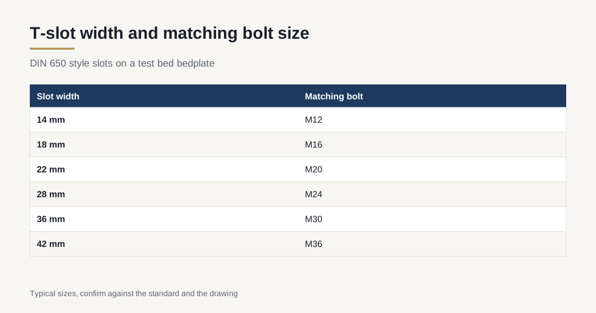
The top surface carries T-slots, rows of precision grooves into which T-bolts slide. They let the engine and dynamometer be positioned and clamped anywhere along the plate. Slot widths follow standards such as DIN 650.
| Slot width | Matching bolt size |
|---|---|
| 14 mm | M12 |
| 18 mm | M16 |
| 22 mm | M20 |
| 28 mm | M24 |
| 36 mm | M30 |
| 42 mm | M36 |
Heavy engines and dynamometers need larger slots and bolts. The slot pitch, the distance between slots, determines how flexibly equipment can be placed. Typical pitches range from 100 to 250 mm, with the choice depending on equipment size.
Slot machining tolerances include width, straightness, parallelism to each other and position relative to the datum axis. A long slot that wanders by half a millimetre makes bolting a base plate awkward and can twist the equipment. Slots are normally milled after stress relief on a large machine, with the whole top face in a single setup.
Tapped holes and drilled grids can replace or supplement T-slots, particularly for gearboxes and electric motors. The positions, thread sizes and depths need to be stated with tolerance.
Flatness, parallelism and alignment
The top surface of the plate is the reference for the entire bench. Typical targets for a test bed bedplate are flatness of about 0.05 to 0.10 mm per metre over the working area and slot parallelism within a few hundredths of a millimetre per metre. A long plate of 6 m may therefore accept deviations of a few tenths of a millimetre across its length. The bench designer’s drawing sets the actual numbers.
Why this matters:
- A dynamometer and engine on a flat plate can be aligned with shims of a few tenths of a millimetre or less.
- A plate that is warped by 1 mm needs thick shim stacks, which compress under load and change alignment.
- Misalignment between engine and dynamometer shafts wears the coupling and shortens bearing life.
Flatness is checked with a precision level, laser tracker or optical alignment system. Ask the shop how and when it measures. The measurement should take place at stable temperature after the plate has been left to equalise, as described in the article on post-weld machining allowance.
Stress relief and machining sequence
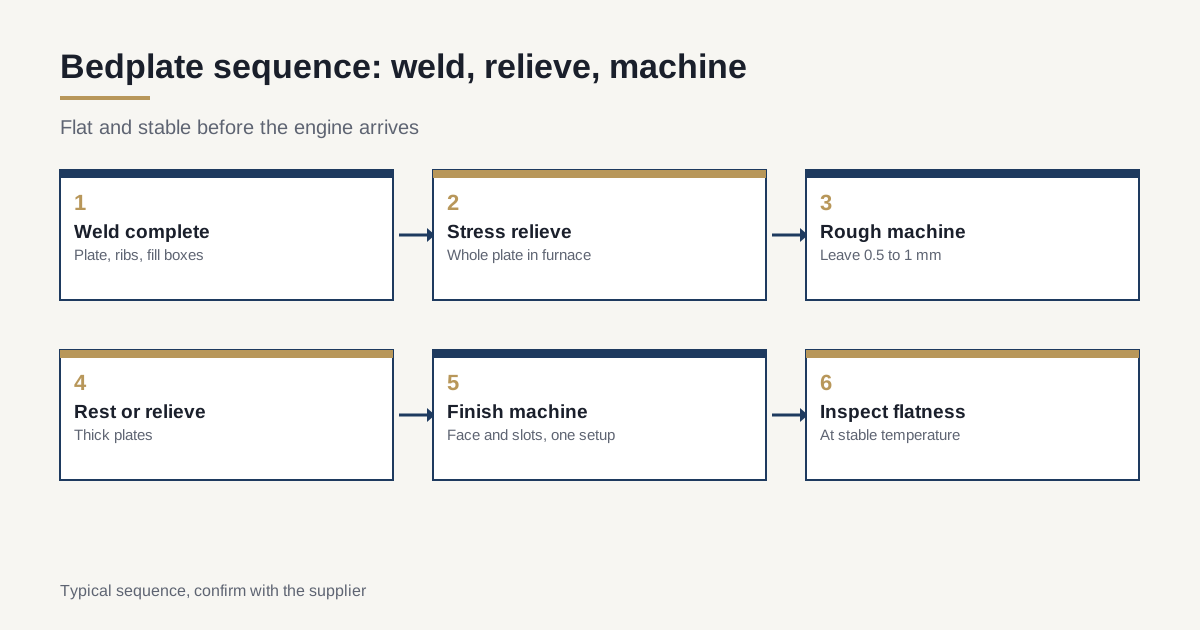
A welded bedplate stores a lot of residual stress. Machining before stress relief will leave a plate that moves. The standard sequence is:
- Weld the plate, ribs and any fill boxes complete.
- Stress relieve the whole plate, in a furnace large enough, or by an agreed alternative. See the article on stress relief for welded machine bases.
- Rough machine the top face and slots, leaving 0.5 to 1 mm.
- Rest or relieve again for very thick plates.
- Finish machine top face, slots, side faces and bores in one setup where possible.
- Inspect flatness, slot geometry and hole positions.
Bore holes for locating pins and bearing pedestals can be line bored if they are aligned, as in the article on line boring bearing housings. Typical stock allowances and datum choices appear in the article on post-weld machining allowance.
Machine capacity is a real limit. A bedplate 6 m long and 2 m wide, weighing 15 tonnes, needs a floor-type or portal machine of that size with a crane to match. Ask for the machine table size and load rating in the quote.
Welding
The top plate is thick, often 40 to 100 mm, and welded to ribs and side plates in full-penetration or deep-groove joints. This is heavy structure with high restraint, so the usual controls apply: qualified procedures, preheat and interpass control, a planned sequence and delayed inspection. See the articles on preheat and interpass temperature, welding distortion control and NDT for heavy weldments.
Where thick plates meet at right angles and weld shrinkage pulls through the thickness, consider Z-grade plate, as covered in the article on Z25 and Z35 steel.
Coating and fluids
Test cells see oil, fuel, coolant and cleaning solvents. The bedplate needs a coating that resists them.
- Machined top face and slots are normally left bare and protected with a rust preventive that is easy to remove.
- Side faces and underside take an oil-resistant epoxy or polyurethane system.
- Drip channels and sumps welded into the plate edge collect spills and should drain to a defined point.
- Seal welds on any hollow section that holds fill or must stay dry.
Masking of the machined faces during coating is a detail that should appear on the drawing. A rust preventive is cleaner for the bench than a paint layer that chips under bolts.
Lifting and installation
Bedplates are lifted with threaded lifting points in the top face or through side lugs. Typical threaded lifting points are M30 or M36 eye bolts in large plates. State the number, size and depth, and check the lifting plan with the crane in the cell. Levelling bolts or jacking screws along the edges let the installer level the plate on its foundation and grout it in place.
Shipping a bedplate of this size usually means a flat rack or breakbulk shipment, as explained in the article on out-of-gauge breakbulk shipping.
What to write on the order
- Drawing with flatness, slot, hole and datum tolerances.
- Material grades, certificates and Z-class where needed.
- Welding procedures and inspection plan, including delayed UT.
- Stress relief and chart delivery.
- Machining capacity statement with machine table and load.
- Inspection method for flatness and slots, with temperature.
- Coating specification with masking.
- Lifting and shipping plan.
Checklist before awarding
- Construction type and any fill or ribbing understood.
- Stress relief furnace size confirmed.
- Machine capacity matches plate size and weight.
- Slot pitch, width and straightness tolerances stated.
- Flatness measurement method defined.
- Coating and masking agreed.
- Lifting and shipping planned.
If you build test benches or run a test lab and need a bedplate fabricated and machined, send the drawing. We reply within 24 business hours.