Gantry Crane and Port Crane Structures: Sourcing Fabricated Sections
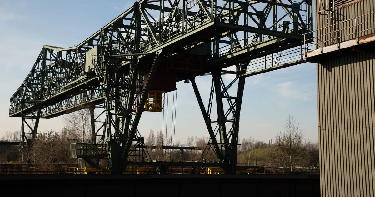
A crane is a machine, and its steel structure is the largest and least mobile part of it. Crane builders in North America, Europe and Australia design and assemble the machine, the drives and the controls, and many buy the welded steel structure from a fabricator. Girders, legs, end carriages, portal frames and boom sections are heavy, long and welded to a standard that is stricter than ordinary building steel because the loads move and repeat.
This article covers what a buyer should know when sourcing fabricated crane sections: the main structural parts, the welding and tolerance points that decide quality, and how to plan splices and shipping.
What the structure consists of
Crane types differ, and so do their fabricated parts.
| Crane type | Typical fabricated parts | Notes |
|---|---|---|
| Single or double girder gantry | Bridge girders, legs, sill beams, end carriages | Common in yards, workshops and precast plants |
| Rail-mounted gantry for container yards | Girder, legs, portal frame, cantilevers | Large spans, high duty cycles |
| Rubber-tyred gantry | Girder, legs, travel frame | Tall, mobile, wind loads matter |
| Ship-to-shore port crane | Portal legs, boom, backreach, girders | Very large sections, heavy plate |
| Semi-gantry and shipyard cranes | One rail on a wall or column, one on legs | Mixed structure types |
Most sections are welded box girders, trusses or tubular frames. A box girder is made from two flange plates and two web plates welded into a closed section, usually with internal diaphragms that keep the shape and carry load into the supports.
Design standards and responsibilities
The crane designer chooses the design standard. Common ones include EN 13001 and the FEM rules in Europe, ISO standards for cranes, and CMAA specifications for overhead and gantry cranes in the US. For welded crane structures, AWS D14.1 and similar crane welding codes set weld quality and procedure rules. The duty class of the crane, which describes how often it lifts near its rated load, sets the fatigue requirements for the structure.
Responsibilities are usually split:
- The crane builder is responsible for the design, calculations, load testing and certification of the finished crane.
- The fabricator builds the steel structure to the drawings and the welding specification, and supplies the documentation.
A fabricator is not a crane maker. Make sure the order states who holds the design responsibility, and who signs the final conformity document.
Fatigue-critical welds
A crane structure is loaded and unloaded thousands of times a year. Fatigue cracks start at weld toes, welded attachments and discontinuities. The welds that matter most are:
- Flange to web joints along the full girder length.
- Flange and web butt splices made in the shop.
- Diaphragm attachment welds near the supports and rail seats.
- Rail support attachment welds, where wheel loads enter the girder.
- Leg to girder and boom to portal connections.
Good practice includes full-penetration welds with root back-gouging or backing in highly stressed butt joints, continuous fillet or deep-penetration welds on the flange-to-web connection and ground weld toes at attachments. Automatic submerged arc welding is common for long flange-to-web seams because it gives consistent depth and a smooth profile. The welding procedures behind these joints should be reviewed, as explained in the article on reading a WPS and PQR.
Material needs thought too. Crane flanges are often 20 to 60 mm plate in S355J2, S355K2 or similar. Where a plate carries through-thickness tension from an attachment weld, a Z-grade is worth considering, as covered in the article on Z25 and Z35 steel. Cold-climate sites may need impact-tested plate, as described in the article on Charpy impact requirements.
Camber, straightness and flatness
Crane girders are built with an upward camber so that they sag to roughly level under the working load. A typical pre-camber is about span divided by 1,000, with the exact value set by the crane designer. The fabricator must build the curve into the girder and verify it, because welding distortion works against it.
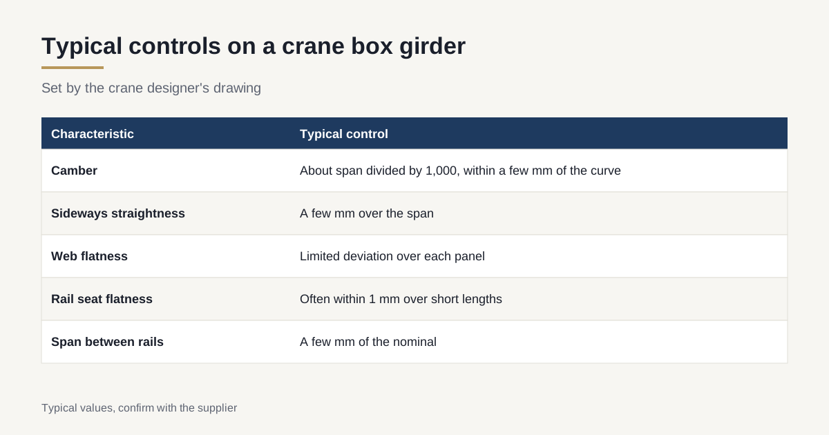
Typical tolerance categories on a box girder are:
| Characteristic | Typical control |
|---|---|
| Camber | Within a few millimetres of the specified curve, measured at several points |
| Sideways straightness | A few millimetres over the span, often a limit such as span divided by 1,500 to 2,000 |
| Web flatness | Limited deviation over each panel, since waviness causes local stress and appearance problems |
| Flange flatness and squareness | Controlled across the width, especially at the rail seat |
| Rail seat flatness | Tight, often within 1 mm over short lengths |
| Overall length and span | A few millimetres, with the span between rails the critical measure |
These are typical values, and the crane designer’s drawing sets the real ones. Distortion control during welding is covered in the article on welding distortion control for heavy plate. Large structures are checked with laser trackers or total stations, as described in the article on dimensional inspection of large frames.
Rail seats and wheel loads
The point where the trolley or crane wheel runs on the structure sees the most concentrated load. Rail seats on girders and travel rails on sill beams must be flat, straight and well supported by the steel below. A rail laid on a wavy flange wears quickly, and a rail seat welded without a diaphragm or stiffener under it can crack the web.
Check three things on the drawing. First, the stiffener or diaphragm directly beneath each rail line. Second, the rail fixing method, whether welded, clipped or bolted, and any clearance requirement for the fixing. Third, the allowed gap and step at rail joints. Fabricators often machine or grind the rail seat flat after welding, so the order should say whether the rail seat is delivered as welded or finished flat to a stated tolerance. The wheel manufacturer’s data sheet gives the loads and rail width the structure must support, and the crane builder should pass it to the fabricator with the drawing.
Splices and sectioning for shipment
Large girders and booms cannot ship whole. A 40 m girder is cut into sections that fit road, rail or ship constraints, and the sections are joined at the crane builder’s yard or on site by bolted or welded splices.
Considerations:
- Splice location away from the highest bending and shear zones, where possible.
- Splice type. Bolted friction connections avoid field welding and are quick to assemble. Welded splices give full continuity but need qualified field welding and inspection.
- Match marking and trial assembly. Sections that meet at a splice should be fitted together in the shop, checked for alignment of plates and holes and match marked before dismantling. See the article on trial assembly before shipment.
- Bolt specification and surface preparation for friction splices, as covered in the article on structural bolts for heavy frames.
- Lifting points and shipping saddles designed for each section.
The wider logic of splitting a frame is covered in the article on split-and-bolt frame design.
Weight, size and shipping
Crane sections are among the longest and heaviest steel parts that move on roads and ships. A girder section can be 20 to 30 m long and weigh 20 to 80 tonnes. A port crane boom section can be heavier still. These parts usually need breakbulk or flat rack shipping, special trailers and route surveys.
Plan the shipping at the start of the project. The envelope, weight and lifting points of each section decide the splice locations and the packing. The practical steps are in the article on out-of-gauge breakbulk shipping.
Coating
Crane structures work outdoors for decades, often in ports and coastal air. The coating system is a long-life marine or heavy-duty system, commonly specified under ISO 12944 for a high corrosivity category, with blast cleaning, zinc-rich primer, intermediate coat and topcoat. Faying surfaces of friction splices are masked or left uncoated according to the connection design. Coating and its inspection are covered in the article on surface finish systems for structural steel.
Inspection and documentation
Crane structures need a strong documentation pack:
- Material certificates with heat number traceability for all main plates.
- Welding procedures, welder qualifications and a weld map.
- NDT reports, typically UT on full-penetration butt welds and MT on fillets and attachments in fatigue-critical zones. See the article on NDT for heavy weldments.
- Dimensional inspection report with camber, straightness and span measurements.
- Coating records with thickness readings and environmental conditions.
- Packing and marking list that ties each section to the assembly drawing.
What to write on the order
- Drawings with design standard and duty class referenced.
- Material grades, certificates and any Z-class or impact requirements.
- Welding specification, including process, qualification and weld quality level.
- Camber and tolerance table with measurement method.
- NDT plan with method, extent and delayed UT where required.
- Splice details, trial assembly requirement and bolt supply.
- Coating specification and inspection hold points.
- Shipping envelope, lifting points and packing.
Checklist before awarding crane sections
- Design and certification responsibility written down.
- Fatigue-critical welds identified on the drawing.
- Camber and straightness tolerances stated with a measurement method.
- NDT plan includes delayed UT.
- Splice and shipping plan agreed before cutting.
- Coating system and inspection points defined.
- Documentation pack content listed.
If you build cranes and want to know which shops have the plate handling, automatic welding and measuring capacity for girders and legs, send the drawing. We reply within 24 business hours.