Hydraulic Press Frames: Weldment Design and Fabrication Checks
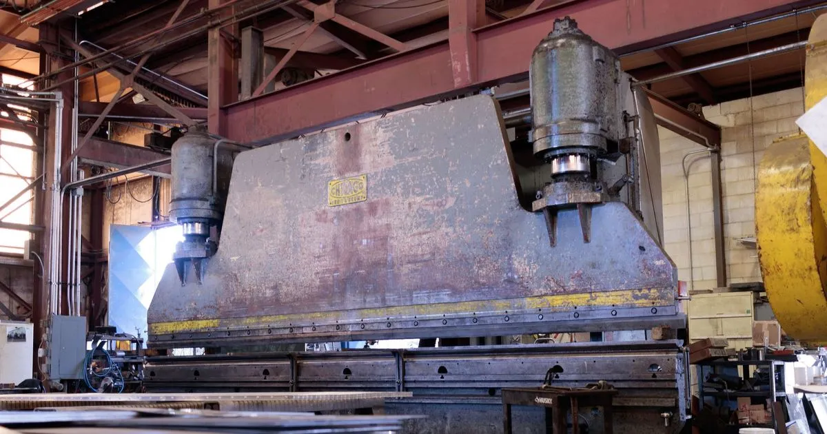
A hydraulic press concentrates a very large force into a small space and then repeats it thousands of times. The frame carries that force on every stroke. It must stay stiff enough to keep the tooling aligned and tough enough to survive years of cyclic loading without cracks growing from the welds. A press frame is therefore not just a heavy steel box. It is a fatigue-loaded precision weldment.
This article covers the common frame types, the design points a buyer should review with the press builder and the fabrication checks to write into the order when the frame is sourced from a welding shop.
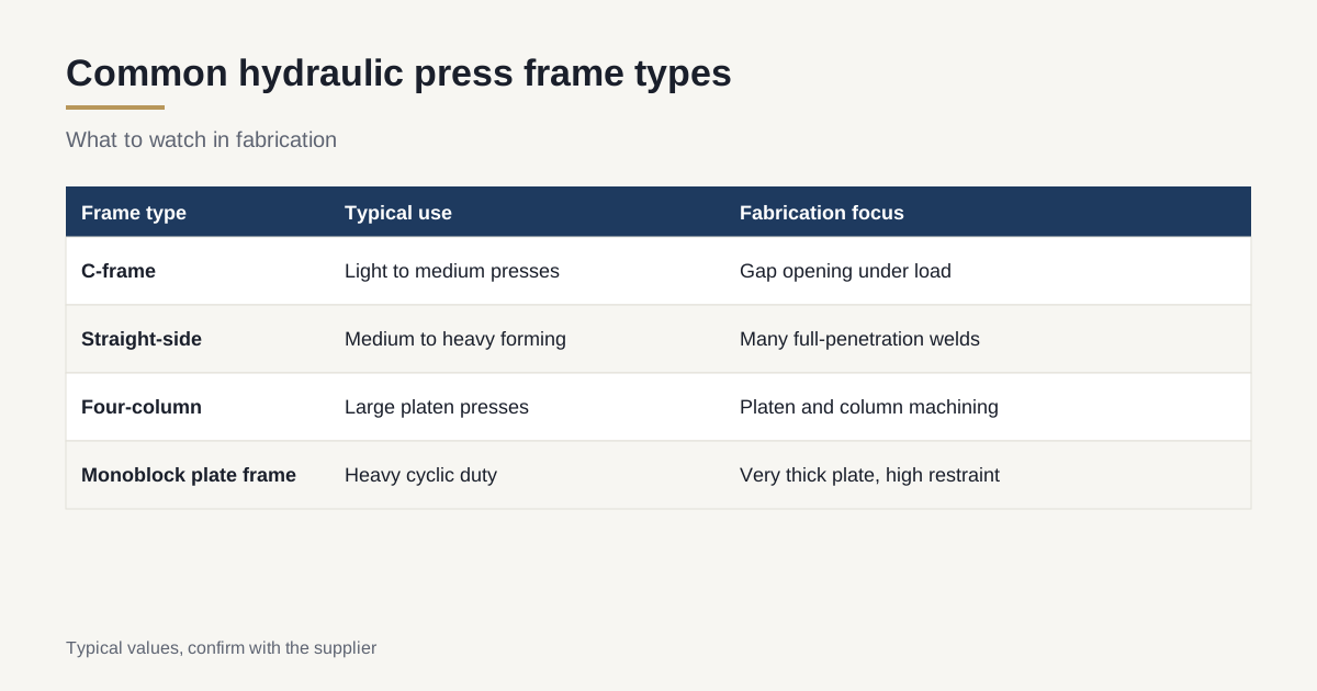
Common frame types
Hydraulic presses use a few standard frame layouts. The choice depends on tonnage, access to the work area and the stiffness required.
| Frame type | Description | Typical use | Fabrication notes |
|---|---|---|---|
| C-frame (open gap) | One-piece C-shaped plate frame with open front | Light to medium presses, straightening, assembly | Gap opens under load, so stiffness and angular deflection matter |
| Straight-side (H-frame) | Two side plates joined by crown and bed | Medium to heavy forming and stamping | Large plates, many full-penetration welds |
| Four-column | Crown and bed held by four tie rods or columns | Large platen presses, composites, forging | Columns and platens machined, tie rods pre-tensioned |
| Monoblock plate frame | Thick plates stacked or welded into one frame | Heavy presses with high cyclic loading | Very thick plate, high restraint |
A welded frame can be built faster than a casting for a single unit or a small series, and it is easier to change in design. Casting suits larger series and some very complex shapes. The trade-off is explained in the article on machined weldment versus casting for a machine base.
Design points to review
The press builder owns the design. A buyer or sourcing desk should still understand the points that drive fabrication cost and risk.
Stiffness and deflection. A press frame stretches under load. Presses are designed so that bed and slide deflection stays within a fraction of a millimetre per metre of working width at rated load, and so that angular deflection of the slide stays small. The exact limits come from the press designer and the product being made. Check that the drawing states them or refers to a design report.
Fatigue. Every stroke is a load cycle. Fatigue cracks start at weld toes, corners and notches. Good frame designs use generous radii at internal corners, full-penetration welds at highly stressed joints, ground weld toes and a thickness transition that avoids sharp steps. The fatigue category for each weld detail follows a standard such as EN 1993-1-9 or the IIW recommendations, and the drawing should carry the weld quality level that goes with it.
Plate orientation and grade. Plates are chosen so that the main stresses run along the rolling direction. Typical structural grades are S355J2 and S355K2, or ASTM A572 Grade 50 and A516 for thicker plate. Joints where thick plates meet at right angles put tension through the thickness of one plate, which makes lamellar tearing a risk. See the article on Z25 and Z35 through-thickness steel. Cold operation or outdoor installation may also call for impact-tested plate, as explained in the article on Charpy impact requirements.
Cylinder and platen interfaces. Cylinder bores, mounting faces and platen surfaces must be flat, parallel and square to each other. These requirements drive the machining plan.
Welding checks
Press frames are welded with thick plate, deep grooves and many passes. The welding plan should be reviewed before the first cut.
- Qualified procedures for each joint type and thickness range, with impact tests if the plate requires them. See the article on reading a WPS and PQR.
- Preheat and interpass control with measured and recorded temperatures. Thick plate in a restrained frame is the typical case for cold cracking, as covered in the article on preheat and interpass temperature.
- Joint design with full penetration at main load paths, with the weld root back-gouged and checked where the design requires it.
- Weld sequence plan that balances shrinkage and limits distortion. See the article on welding distortion control for heavy plate.
- Weld finish: toes ground smooth at fatigue-critical joints, and notches and undercut removed.
A shop that welds presses regularly will have a weld map, a numbered list of joints with the procedure, the welder and the inspection result for each. Ask to see an example from a previous job.
Stress relief and machining
Press frames are almost always stress-relieved before machining. The residual stress in a thick, restrained weldment is high, and machining the cylinder bore or platen face releases it. A frame that moves after machining can lose parallelism between bed and crown.
The usual sequence is:
- Weld the frame complete.
- Stress relieve in a furnace large enough for the whole frame, or in sections if the design is split. The practice is explained in the article on stress relief for welded machine bases.
- Rough machine the main faces and bores.
- Rest the frame, and relieve again if the stock removal is heavy.
- Finish machine faces, bores and platen surfaces from datums defined on the drawing.
Furnace size is a real constraint. A frame 4 m long and 3 m high needs a furnace of that size or larger. Ask the shop where the stress relief will be done, and whether a subcontractor is involved. Datum and allowance planning is covered in the article on post-weld machining allowance, and bore alignment in the article on line boring bearing housings.
Typical machining tolerances for press frames are parallelism of bed and crown mounting faces in the range of 0.05 to 0.10 mm per metre, and flatness of platens at a similar level. The press designer sets the real values.
Inspection plan
Full-penetration welds in a fatigue-loaded frame justify more inspection than ordinary structure. A typical plan is:
| Inspection | Scope | Timing |
|---|---|---|
| Visual | All welds | During and after welding |
| Magnetic particle | Fatigue-critical toes and corners, all stress-relieved welds | After stress relief |
| Ultrasonic | All full-penetration welds on main load paths | After a delay of 24 to 48 hours on thick joints |
| Dimensional | Overall frame and machined faces | Before and after machining |
| Material certificates | All main plates, heat numbers traced | Before cutting |
The methods and acceptance levels are described in the article on NDT for heavy weldments. Large frames are measured with a laser tracker or a large measuring arm, as covered in the article on dimensional inspection of large frames.
Where press frames fail in service
Knowing the usual failure points helps a buyer ask better questions. Three show up most often in press frames that crack.
Cracks at weld toes in the corner between side plate and crown. The corner sees the highest bending stress on every stroke. Cracks start at the toe of a weld that was left as welded, with undercut or a sharp transition. The prevention is a smooth, ground toe, a generous radius and full-penetration welding backed by ultrasonic testing.
Cracks from lack of fusion in thick joints. A deep groove welded with too little heat or a poor bead sequence can hide unfused zones that ultrasonic testing finds and visual inspection does not. This is why the inspection plan covers every full-penetration weld on a main load path and not a sample.
Loose or uneven tie rods and bolted joints. On four-column presses and split frames, bolt or rod preload below the working load lets the joint open on each stroke and fatigues the fasteners. The preload value and the tightening method belong in the assembly instructions, and the bolting basics are covered in the article on structural bolts for heavy frames.
None of these is exotic. Each is controlled by documented welding, inspection and assembly steps, which is why the order should ask for records and not only for a finished frame.
Weight, lifting and shipping
Press frames are among the heaviest fabrications a sourcing desk handles. A 500-tonne press frame can weigh 20 to 40 tonnes, and larger presses weigh far more. Lifting lugs, centre of gravity and transport envelope must be planned from the start. Frames often ship in sections and are bolted or welded together at the press builder’s plant. The shipping planning is explained in the article on out-of-gauge breakbulk shipping.
Responsibilities and standards
The press builder is responsible for the machine design and for compliance with press safety standards such as EN 693 for hydraulic presses or the applicable US rules. The fabricator is responsible for building the frame to the drawing. A frame supplied to a drawing is not a certified press. Make the split of responsibilities clear on the order: who provides the design calculation, who approves welding procedures and who signs off the inspection.
What to write on the order
- Drawing and design report reference, including the fatigue category of the main welds.
- Material grades with certificates, including Z-class and impact requirements where needed.
- Welding procedures and records, with a weld map.
- Stress relief, with method, furnace location and chart delivery.
- Machining tolerances and datum scheme.
- Inspection plan with NDT methods, extent and delay.
- Documentation pack: certificates, weld records, NDT reports, dimensional report, stress relief charts.
Checklist before awarding the job
- Frame type and fatigue-critical joints identified.
- Material, Z-class and impact requirements stated.
- Welding procedures and sequence reviewed.
- Stress relief furnace size confirmed.
- Machining capacity matches the frame size and weight.
- NDT plan includes delayed UT.
- Shipping and lifting planned.
If you have a press frame drawing and want to know which shops can weld, relieve and machine it, send the drawing. We reply within 24 business hours.